


Shopping cart is empty!
All Projects, Arduino Projects, Core Electronics Projects, Electrical Projects, Core Electrical Projects
11 Level Multilevel Inverter
4.8 ★
4.8 ★
5 Ratings
5 ★
4
4 ★
1
3 ★
0
2 ★
0
1 ★
0
(5)
Highlights:
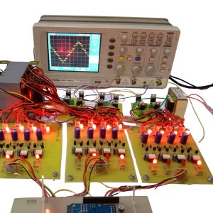
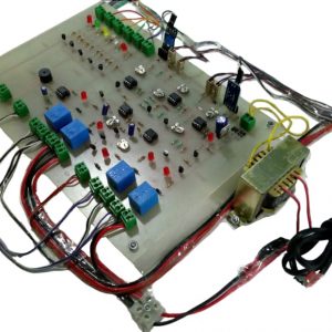
This project presents the hardware implementation of the single phase ??in eleven ??level multilevel inverter using the Cascaded HBridge using Separated DC sources. The main objective of is to increases the number of levels with a lower number of switches at the output without adding any complexity to the power circuit
Highlights:
This project presents the hardware implementation of the single phase ??in eleven ??level multilevel inverter using the Cascaded HBridge using Separated DC sources. The main objective of is to increases the number of levels with a lower number of switches at the output without adding any complexity to the power circuit
All Projects, Automation Projects, Android Projects, Mechanical Projects, Robotics Based Projects, Mechatronics
360 Degree Steering Mechanism
4.8 ★
4.8 ★
4 Ratings
5 ★
3
4 ★
1
3 ★
0
2 ★
0
1 ★
0
(4)
Highlights:
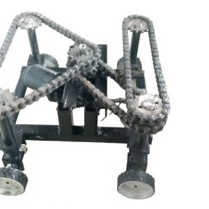
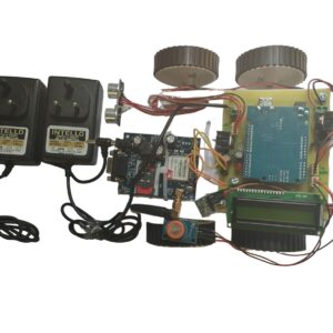
Main objective of this project is to develop a steering mechanism that vehicle will be steered at single position.
₹17,000.00 ₹20,000.00 15% Off
Highlights:
Main objective of this project is to develop a steering mechanism that vehicle will be steered at single position.
All Projects, Arduino Projects, Core Electronics Projects, Electrical Projects, Core Electrical Projects, Electronic Products
7 Level Multilevel Inverter
4.7 ★
4.7 ★
7 Ratings
5 ★
5
4 ★
2
3 ★
0
2 ★
0
1 ★
0
(7)
Highlights:
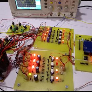
This project presents the hardware implementation of the single phase ??in seven level multilevel inverter using the Cascaded HBridge using Separated DC sources. The main objective of is to increases the number of levels with a lower number of switches at the output without adding any complexity to the power circuit.
Highlights:
This project presents the hardware implementation of the single phase ??in seven level multilevel inverter using the Cascaded HBridge using Separated DC sources. The main objective of is to increases the number of levels with a lower number of switches at the output without adding any complexity to the power circuit.
All Projects, Arduino Projects, Electrical Projects, Core Electrical Projects, Power Electronics, Bluetooth Based Projects
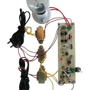
AC DIMMER OF TWO LOADS USING SINGLE CONTROLLER
4.7 ★
4.7 ★
3 Ratings
5 ★
2
4 ★
1
3 ★
0
2 ★
0
1 ★
0
(3)
Highlights:
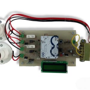
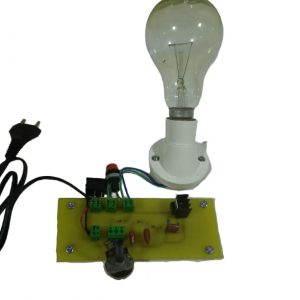
This project is intended to attain AC dimmer of two loads using single controller. It is a renowned and aged technique of managing AC power, principally across linear loads for instance heaters brought into play in electric oven.
In this project, we are using a comparator for zero crossing detection which is fed as an interrupt to the arduino UNO3. Here, the arduino delivers the output based on the interrupt received as the reference for generating triggering pulses. Using these pulses, we drive the Opto-isolators for triggering the TRIAC to achieve integral cycle control as per the input switches interfaced to the arduino. In place of a linear load to be used in the output, a series motor or lamp can be used to verify the output. A lamp is provided in this project in place of a motor for demonstration purpose. The project output with a lamp appears to be a simple project of lamp flickering but the real objective is to verify in a CRO/DSO ,whether at the random switching also the load switches on at zero cross of the waveform or not.
Highlights:
This project is intended to attain AC dimmer of two loads using single controller. It is a renowned and aged technique of managing AC power, principally across linear loads for instance heaters brought into play in electric oven.
In this project, we are using a comparator for zero crossing detection which is fed as an interrupt to the arduino UNO3. Here, the arduino delivers the output based on the interrupt received as the reference for generating triggering pulses. Using these pulses, we drive the Opto-isolators for triggering the TRIAC to achieve integral cycle control as per the input switches interfaced to the arduino. In place of a linear load to be used in the output, a series motor or lamp can be used to verify the output. A lamp is provided in this project in place of a motor for demonstration purpose. The project output with a lamp appears to be a simple project of lamp flickering but the real objective is to verify in a CRO/DSO ,whether at the random switching also the load switches on at zero cross of the waveform or not.
All Projects, Core Electronics Projects, Electrical Projects, Core Electrical Projects, Power Electronics, Mini Project, Electronic Products
AC DIMMER TO CONTROL AC VOLTAGE, SPEED OF INDUCTION MOTOR OR HEATER COIL
4.5 ★
4.5 ★
2 Ratings
5 ★
1
4 ★
1
3 ★
0
2 ★
0
1 ★
0
(2)
Highlights:
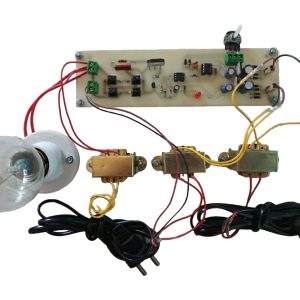
A??voltage controller, also called an??AC voltage controller??or??AC regulator??is an electronic module based on either??thyristors,??TRIACs,??SCRs??or??IGBTs, which converts a fixed voltage, fixed frequency??alternating current??(AC) electrical input supply to obtain variable??voltage??in output delivered to a resistive??load.
Induction motor speed control is done by varying the frequency of the applied voltage. Raising or lowering the voltage can have some speed control effects but these will be small, difficult to control, load-dependent, possibly cause the motor to overheat and, are not generally recommended.
Highlights:
A??voltage controller, also called an??AC voltage controller??or??AC regulator??is an electronic module based on either??thyristors,??TRIACs,??SCRs??or??IGBTs, which converts a fixed voltage, fixed frequency??alternating current??(AC) electrical input supply to obtain variable??voltage??in output delivered to a resistive??load.
Induction motor speed control is done by varying the frequency of the applied voltage. Raising or lowering the voltage can have some speed control effects but these will be small, difficult to control, load-dependent, possibly cause the motor to overheat and, are not generally recommended.
All Projects, Sensor Based Projects, Arduino Projects, Communication, GSM Based Projects, Electronic Products
ACCIDENT DETECTION BY USING ACCELEROMETER ALCOHOL SENSOR GSM
4.7 ★
4.7 ★
3 Ratings
5 ★
2
4 ★
1
3 ★
0
2 ★
0
1 ★
0
(3)
ACKERMAN STEERING MECHANISM
4.5 ★
4.5 ★
2 Ratings
5 ★
1
4 ★
1
3 ★
0
2 ★
0
1 ★
0
(2)
Highlights:
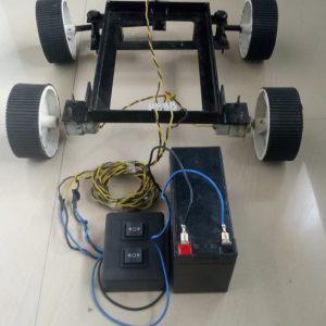
There are many types o steering mechanisms used in automotive vehicles. In this project we have made prototype of Ackerman steering mechanism.
₹9,500.00 ₹10,500.00 10% Off
Highlights:
There are many types o steering mechanisms used in automotive vehicles. In this project we have made prototype of Ackerman steering mechanism.
ACPWM power control using 555IC and IGBT
4.3 ★
4.3 ★
4 Ratings
5 ★
2
4 ★
1
3 ★
1
2 ★
0
1 ★
0
(4)
Highlights:
This project attempts a new speed control technique for the single-phase a.c. induction motor. It presents a design of a low-cost; high-efficiency drive capable of supplying a single-phase a.c. induction motor with a PWM modulated sinusoidal voltage. The circuit operation is controlled by 555 astable multivibrator. The device is aimed at substituting the commonly used triac phase angle control drives. The circuit is capable of supplying a single-phase a.c. induction motor (or general a.c. inductive/resistive load) with varying a.c. voltage.
All Projects, LDR Sensor Based Projects, Sensor Based Projects, Thermistor Sensor Based Projects, Arduino Projects, Core Electronics Projects, Electrical Projects, Ultrasonic Based Projects, Electronic Products
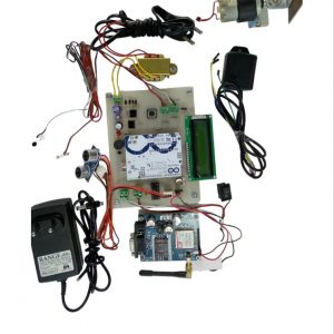
ADVANCE ATM SECURITY SYSTEM
4.7 ★
4.7 ★
3 Ratings
5 ★
2
4 ★
1
3 ★
0
2 ★
0
1 ★
0
(3)
Highlights:
The Idea of Designing and Implementation of Security Based ATM theft project is born with the observation in our real life incidents happening around us. This project deals with prevention of ATM theft from robbery. So overcome the drawback found in existing technology in our society. Vibration sensor is used here which senses vibration produced when ATM machine is hammered. This system uses Arduino based system to process real time data collected using the vibration sensor. Once the vibration is sensed the beep sound will occur from the buzzer. DC Motor is used for closing the door of ATM and send with the message to the nearby police station and corresponding authorized person through the GSM.
All Projects, Electrical Projects, Mechanical Projects, Embedded Projects, Micro Controller, Mechatronics
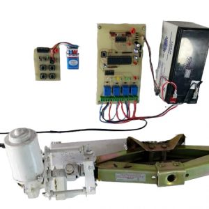
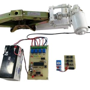
ADVANCE CAR JACK CONTROLLED BY RF WIRELESS DEVICE
4.5 ★
4.5 ★
12 Ratings
5 ★
6
4 ★
6
3 ★
0
2 ★
0
1 ★
0
(12)
Highlights:
The project is designed to control the direction of car jack by using a RF technology for remote operation with a transmitter and receiver. The direction of the DC motor is depending on signal which is coming from transmitter. Hence, if the relay 1 & relay 4 gets ON then the motor rotates in forward direction. And if relay 2 & relay 3 gets ON then the motor rotates in backward direction.
All Projects, Rain Sensor Based Projects, LDR Sensor Based Projects, Thermistor Sensor Based Projects, Sensor Based Projects, Soil Moisture Sensor Based Projects, IR Based Projects, Core Electronics Projects, Electrical Projects, Temprature Based Projects, School project
ADVANCE GREEN HOUSE WITHOUT MICROCONTROLLER
4 ★
4 ★
2 Ratings
5 ★
1
4 ★
0
3 ★
1
2 ★
0
1 ★
0
(2)
Highlights:
This project is designed to monitor the green house using Comparator IC. Various sensors are used to monitor the system. The sensors used are Rain sensor, Soil moisture sensor, LDR, wired security sensor, water level indicator, IR sensor. When the soil of the green house becomes dry the pump will turn on through which the water is let into the soil and the soil regains its moisture. While supplying the water to the dry soil the water level in tank will be reducing simultaneously which will be indicated by the LED???s.
So when the water level reduces below the threshold level the pump will off automatically to avoid dry run.
All Projects, Sensor Based Projects, Arduino Projects, Core Electronics Projects, Electrical Projects, Ultrasonic Based Projects, Mini Project, School project, Electronic Products
ADVANCED BLIND STICK USING ARDUINO
4.3 ★
4.3 ★
4 Ratings
5 ★
1
4 ★
3
3 ★
0
2 ★
0
1 ★
0
(4)
Highlights:
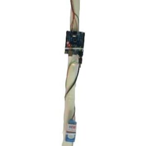
The system consists of obstacle detection sensors for receiving, processing, and sending signals to the alarm system which finally alerts the user for prompt action.
Highlights:
The system consists of obstacle detection sensors for receiving, processing, and sending signals to the alarm system which finally alerts the user for prompt action.