


Description
In this proposed system, two zero crossing detectors are used for detecting zero crossing of voltage and current. The project is designed to minimize penalty for industrial units using automatic power factor correction unit. The PIC microcontroller used in this project .
The time lag between the zero-voltage pulse and zero-current pulse is duly generated by suitable operational amplifier circuits in comparator mode is fed to two interrupt pins of a microcontroller. The program takes over to actuate appropriate number of relays from its output to bring shunt capacitors into load circuit to get the power factor till it reaches near unity. The capacitor bank and relays are interfaced to the microcontroller using a relay driver. It displays time lag between the current and voltage on an LCD. Furthermore, the project can be enhanced by using thyristor control switches instead of relay control to avoid contact pitting often encountered by switching of capacitors due to high in rush current.
Note
APFC using PIC microcontroller for industrial use to minimize penalty is the project for the last year engineering student for the electrical department use for this project. This project is use for the electronics engineering student is use for this project.it is use for the power electronics student for the BE final year student.
APFC using pic microcontroller is the project for the good project, excellent project for the BE last year engineering student. APFC is the project for the competitive project in the BE last year engineering student for electrical, electronics, power electronics student in last year engineering student.
The last year engineering projects, diploma last year, BE last year engineering project give in the project in the ELECTROSAL HI- TECH PVT.LTD. This is the give in the project is best place of the degree and diploma final year engineering projects as well as for electronics student’s and electrical final year student for the golden opportunity.
Automatic power factor correction using PIC microcontroller it is the project and idea for the electrical, electronics and power electronics last year engineering student
HIGHLIGHTS
1 To understand the sensing device of control system
- To design a PIC microcontroller based correction equipment to improve the power factor of the system
- To analyze the system performance with and without compensator installed.
BLOCK DIAGRAM
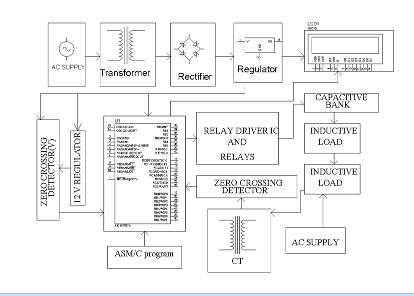
HARDWARE REQUIREMENTS
- TRANSFORMER (230 – 12 V AC)
- VOLTAGE REGULATOR
- RECTIFIER
- FILTER
- PIC microcontroller 16f877a
- RELAY
- RELAY DRIVER
- PUSH BUTTONS
- LCD
- LM339
- CURRENT TRANSFORMER
- INDUCTIVE LOAD
- SHUNT CAPACITOR
- LED
- 1N4007 / 1N4148
- RESISTOR
- CAPACITOR
SOFTWARE REQUIREMENTS
- MP-LAB
- Eagle
- Proteus

Sneha mane –
Project is very nice.
Sneha mane –
Excellent
sneha kamat –
AUTOMATIC POWER FACTOR CORRECTION USING PIC- MICROCONTROLLER this project is very good.
Chaya mane –
good
Vijay Yadav –
Very good service .. thanks to electrosal team they helped me whenever i needed .. sir’s way of explanation of project is appreciable ..