Description
ABSTRACT
The main concept of this inverter is to use diodes and provides the multiple voltage levels through the different phases to the capacitor banks which are in series. A diode transfers a limited amount of voltage, thereby reducing the stress on other electrical devices. The maximum output voltage is half of the input DC voltage. It is the main drawback of the diode clamped multilevel inverter. This problem can be solved by increasing the switches, diodes, capacitors. Due to the capacitor balancing issues, these are limited to the three levels. This type of inverters provides high efficiency because of the fundamental frequency used for all the switching devices and it is a simple method of the back to back power transfer systems.
HIGHLIGHTS
There are number of objectives need to be achieved by end of this project.
- The objectives are: Ø Reduce the harmonics produced by the switching trust and control complexity.
- Reduce the number of power switches usage to reduce the switching losses.
- Reduce the circuit complexity of the H-bridge multilevel inverter.
- Reduce the overall production cost of the inverter due the high usage of power switches
BLOCK DIAGRAM
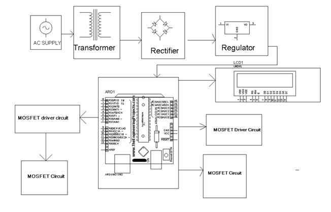
HARDWARE REQUIREMENTS
Hardware Requirements
- ARDUINO controller
- LCD
- MOSFIT Driver Switching circuit
- Relay Driver IC
- Transformer
- Diodes
- Voltage Regulator
- Resistors
- Capacitors
- LEDs
- MOSFITT Circuit
- Power Supply
- switches
SOFTWARE REQUIREMENTS
- Arduino program





Prince mohite –
A brilliant experience with electrosal. They have excellent staff.
Dhanaji Shirke –
good