


This project presents the hardware implementation of the single phase ??in eleven ??level multilevel inverter using the Cascaded HBridge using Separated DC sources. The main objective of is to increases the number of levels with a lower number of switches at the output without adding any complexity to the power circuit. The main advantages of the proposed method are to reduce the Total Harmonic Distortion, lower order harmonics and electromagnetic interference and to get high output voltage. To minimize the total harmonic distortion equal area criteria (EAC) switching technique is presented and it can enhance the output voltages from proposed work. The Inverter is operated by using Arduino controller which generates PWM pulses. The use of Arduino makes the process of using electronics in multidisciplinary projects more accessible. It is well suited for processing control parameters such as speed of an Induction Motor.
This basically focusses on the design and implementation of a topology for a three phase eleven level cascaded H-bridge multilevel inverter by employing different kinds of switching methods. The basic purpose of this work is to increase the number of voltage level at the output withreduction of complexity to power circuit. The main advantages of this proposed topology is to reduce the Total Harmonic Distortion and minimise electromagnetic interface EMI generation and high voltage with very nearly to sine waveform. In this work, several kinds of carrier pulse width modulation techniques are proposed as which reduced the total harmonic distortion and improve the out voltage from the proposed topology and POD modulation techniques reduce the Total Harmonic Distortion. A number of H-bridge arranged in cascade form to increase the voltage level with the different switching schemes It is observed that this new topology can be recommended to three phase eleven level cascaded H-bridge inverter for getting optimum performance over the conventional methods. This performance in optimized in the eleven level of inverter. Improving the fundamental waveforms and reducing the total harmonic distortion is achieved by Utilizing 60 IGBTs and switching is arranged by a topology in cascaded form. The simulation model is produced by MATLAB 2018 software version.
??
??
??
HIGHLIGHTS
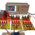
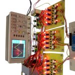
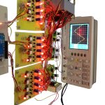
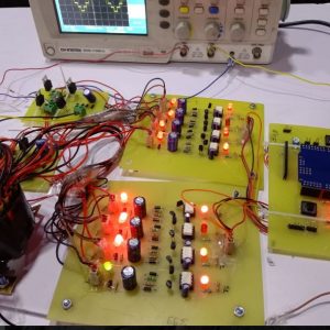
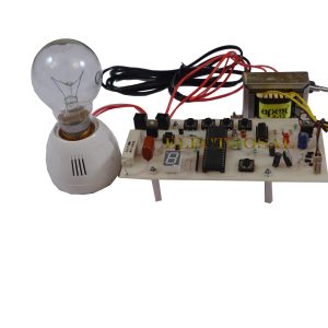
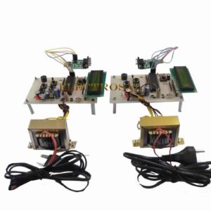
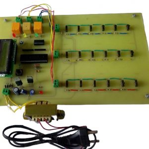
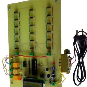
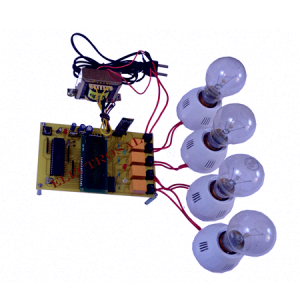
- An experimental investigation has been carried out on single-phase multilevel inverter to obtain 11 level output voltage using cascaded four H-bridge units.
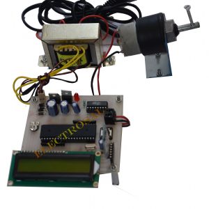
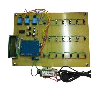
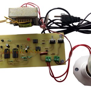
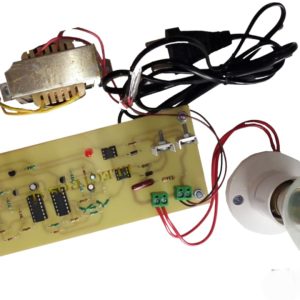
- The proposed system consists of four cascaded H-bridge MOSFET-based voltage source inverters, a microcontroller-based Arduino module, four separate input dc sources and isolating circuit.
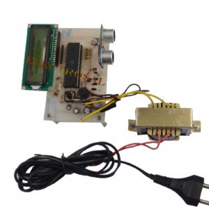
- The gate drive signals for MOSFETs of the four H-bridge inverters are generated by using ATmega Arduino board.
- The microcontroller has been used to reduce the complexity of generating gate drive signals for higher levels of inverter output voltage.
- Different-level output voltages have been obtained from experimental works. It is found that the proposed system requires less number of power switching devices and total harmonic distortion is reduced with increasing number of levels at the output voltage of the multilevel inverter.
??
BLOCK DIAGRAM

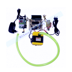
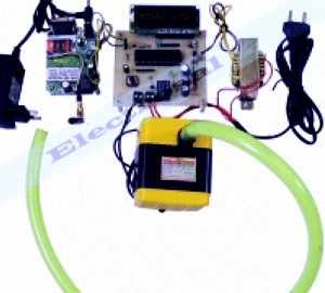
HARDWARE REQUIREMENTS
- Transformer
- Power supply
- Arduino
- LCD
- Inverter
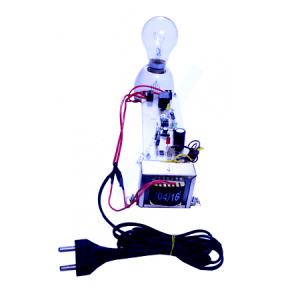
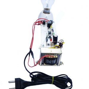
- Load
- MOSFET Driver Ckt
SOFTWARE REQUIREMENTS
- PROTEUS
- EAGLE
- ARDUINO IDE

sonam khot –
electrosal company is very good. project is very nice.
sunita sutar –
Excellent.
Shantosh kawale –
Online customer support by the electrosal support team is quite promising.
natasha malage –
good
Poonam Kamble –
Good experience from electrosal . Projects is very excellent.