


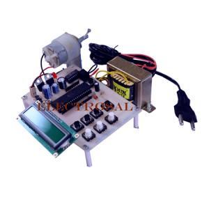
In this proposed system, Automatic Power Factor Correction with measurement of real power, reactive power, and apparent power.?? Two zero crossing detectors are used for detecting zero crossing of voltage and current.
The project is designed to minimize penalty for industrial units using automatic power factor correction unit.
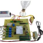
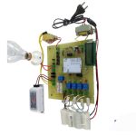
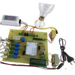
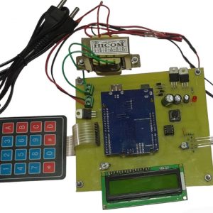
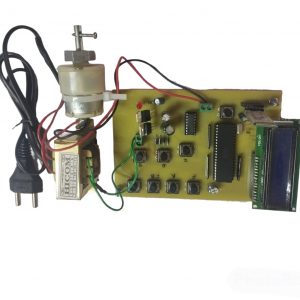
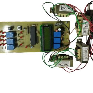
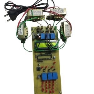
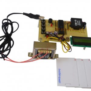
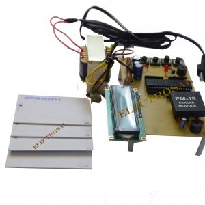
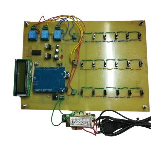
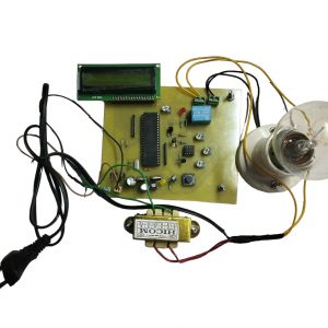
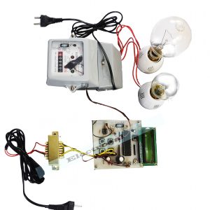
The time lag between the zero-voltage pulse and zero-current pulse is duly generated by suitable operational amplifier circuits in comparator mode and is fed to two interrupt pins of an arduino. The program takes over to actuate appropriate number of relays from its output to bring shunt capacitors into load circuit to get the power factor till it reaches near unity. The capacitor bank and relays are interfaced to the arduino using a relay driver. It displays time lag between the current and voltage on an LCD. Furthermore, the project can be enhanced by using relay control to avoid contact pitting often encountered by switching of capacitors due to high in rush current.
Note
Automatic power factor correction with measurement of real power, reactive power, and apparent power is the project of a good Price for the electrical engineering project. Power Electronics engineering project it is a very comparative engineering project. It is a very good BE final year and diploma project.it is project for arduino based project idea for the core electrical projects is a project power electronics based projects.
The engineering projects give in the ELECTROSAL HI- TECH PVT.LTD. The best place for the degree and diploma final year engineering projects as well as for electrical students ???and core electrical students and power electronics?? final year for the golden opportunity.
Automatic power factor correction with measurement of real power, reactive power, apparent power is an easy project and??idea for the electrical core electrical, power electronics degree and diploma base students & 100% output is done.
HIGHLIGHTS
- Arduino based project
- The project is designed to minimize penalty for industrial units using automatic power factor correction unit.
- Zero crossing detector concept is used.
- APFC panels help reduce Reactive Power and Apparent Power Demand.
- These panels also help to avoid Power Factor Surcharges & Maximum Demand Penalties.
- It reduces the risk of Operational Issues and Power Loss.
BLOCK DIAGRAM

HARDWARE REQUIREMENTS
- arduino
- Op-amps
- LCD
- Shunt Capacitors
- Relays
- Relay driver IC
- Choke
- Crystal
- Switches
- Resistors
- Capacitors
- Diodes
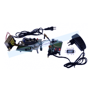
- Transformer
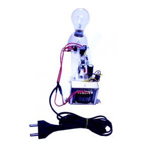
- Lamp
- Voltage Regulator
SOFTWARE REQUIREMENTS
- Arduino
- Eagle
- Protious
??


Arati Deshapande –
A Typical day at work very competitve learned to never to take the objection of one call in to the next management was very encour again when was an off day the morel of the very work was the hards part of the job was tring the leards of the team form month to much the most enjoble part of my job three was the great bounes i received for over achivment
Abhishek dhanaappagol –
Well i got the ARDUINO BASED UNDERGROUND CABLE FAULT DETECTION project and i was surprised to see it delivered in such a good condition. I was afraid that sending a delicate circuit in through international shipping may damage it, but their packaging is extremely good.
Raghu Bell –
Electrosal Hi Tech pvt Ltd is one of the project centre. They provide practical based knowledge of project. Electrosal team are very good and experienced. Thanks electrosal.
Priya Kumar –
I needed a electrical project for final year so I went for this project, the project was well tested also it is in plug and play condition. And it???s impressive as it gives almost accurate results.
Abhi joshi –
Nice customer support .thank for online video call support. thank you Electrosal.