


Description
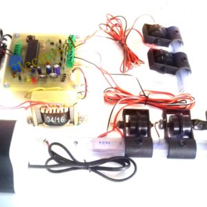
A simple but very reliable and effective water level controller circuit diagram is shown here. The circuit uses 6 transistors, 1 NE555 timer IC, a relay and few passive components. The circuit is completely automatic which starts the pump motor when the water level in the over head tank goes below a preset level and switches OFF the pump when the water level in the over head tank goes above the full level.
Probe D is positioned at the bottom level of the tank while probes A, B and C are placed at full, half and medium levels of the tank respectively. The level sensing part of the circuit is built around transistors Q1, Q2 and Q3. When water level is below the quarter level probes A, B and C are open and the transistor Q1, Q2 and Q3 remains OFF. When the water level rises and touches the probes the corresponding transistors gets biased and switches ON. Resistors R1, R2, R3 limit the bases current of corresponding transistors while resistors R4, R5, R6 limit their collector current. LEDs D1, D2 and D3 provide a visible indication of the current water level.When the water level goes below medium, transistor Q2 gets switches OFF and its collector goes positive. Collector of Q2 is connected to the base of transistor Q6 and as result transistor Q6 gets switched ON. Transistor Q5 will be also ON because its base in connected to the collector of Q4 which is presently OFF. As a result when the water level goes below medium relay K1 gets energized and the pump is driven. The relay is wired in the latching mode so that even if the water level goes above medium level the pump remains ON so that the tank gets completely filled. For wiring the relay in latching mode one set of N/O contacts is used. When relay is activated these contacts close which forms a short across collector and emitter of Q6. This makes the state of Q6 irrelevant to the operation of the relay and the relay remains ON as long as the transistor Q5 is ON. The only way to make the relay OFF is by switching OFF Q5 and it is done automatically when the water level reaches the full level.Collector of transistor Q1 is connected to the trigger pin (pin2) of IC1. When the water level reaches full level the transistor Q1 gets switched ON. As a result its collector goes to ground level which triggers the IC1 which is wired as a monostable. The output of IC1 goes high for about 1S. This makes the transistor Q4 ON for the same time and transistor Q5 whose base is connected to the collector of Q4 is switched OFF cutting the supply to the relay. This makes the motor OFF and it remains OFF until the water level again goes below the medium level.Resistor R8 is a pull up resistor for the trigger pin of the NE555. Capacitor C3 couples the collector of Q1 to the trigger pin of NE555 and facilitates edge triggering whenever the transistor Q1 goes ON. A monostable circuit can be made edge triggered by connecting the trigger signal to the trigger input pin through a capacitor. The capacitor blocks DC and passes sudden changes. The circuit used here is termed as negative edge triggered because the monostable is triggered when ever the trigger input signal falls. R10 and R12 limits the collector current of Q4 and Q5 respectively while R9 and R11 limits their base current. R13 limits the base current of Q6 while D4 is a freewheeling diode which protects the switching transistors from voltage transients.
HIGHLIGHTS
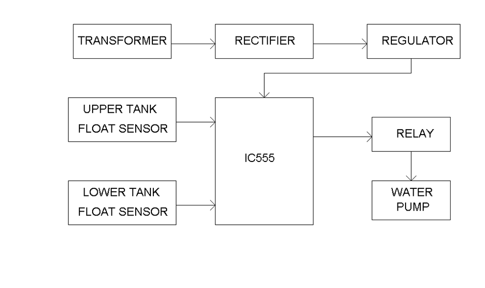
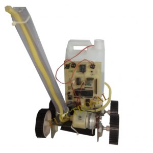
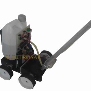
- Float sensors are used to detects the water levels.
- Automatically controlling the water motor by sensing the water level in a tank
- Using this we can avoid the overflow of the water.
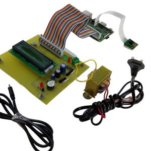
- LCD is to show the water levels of tanks.
BLOCK DIAGRAM
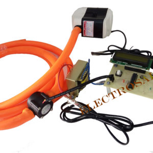
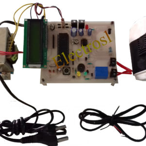
HARDWARE REQUIREMENTS
- Water Pump
- Float sensors
- Water tanks
- Transformer
- LCD display
SOFTWARE REQUIREMENTS
- Eagle

Rupesh kumbhar –
good
Amar Birange –
This website has enormous features especially the DIY kit and but i want project according to my requirements and they provided me such good tested kit along with it one DIY.they give me confidance to build myself without any external help, best self learning kit, technical team responded very well and supported in my output.thank you Electrosal.
Lohith royal –
I have purchased a project from electrosal Hi-tech pvt. Ltd. The project was extraordinary the kit presented in video was excellent