Showing 1–16 of 83 results
-
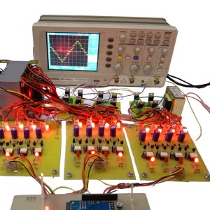
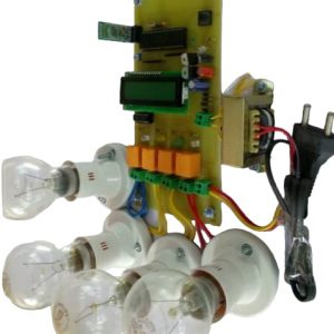
11 Level Multilevel Inverter
$180.30$168.28This project presents the hardware implementation of the single phase in eleven level multilevel inverter using the Cascaded HBridge using Separated DC sources. The main objective of is to increases the number of levels with a lower number of switches at the output without adding any complexity to the power circuit
-
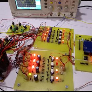
7 Level Multilevel Inverter
$144.24$132.22This project presents the hardware implementation of the single phase in seven level multilevel inverter using the Cascaded HBridge using Separated DC sources. The main objective of is to increases the number of levels with a lower number of switches at the output without adding any complexity to the power circuit.
-
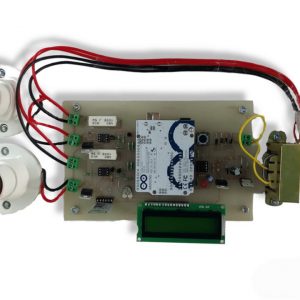
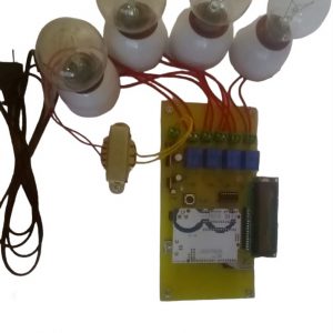
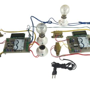
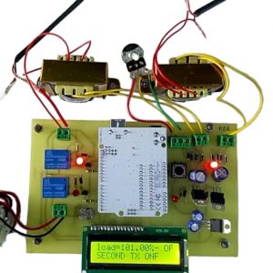
AC DIMMER OF TWO LOADS USING SINGLE CONTROLLER
$102.17$72.12This project is intended to attain AC dimmer of two loads using single controller. It is a renowned and aged technique of managing AC power, principally across linear loads for instance heaters brought into play in electric oven.
In this project, we are using a comparator for zero crossing detection which is fed as an interrupt to the arduino UNO3. Here, the arduino delivers the output based on the interrupt received as the reference for generating triggering pulses. Using these pulses, we drive the Opto-isolators for triggering the TRIAC to achieve integral cycle control as per the input switches interfaced to the arduino. In place of a linear load to be used in the output, a series motor or lamp can be used to verify the output. A lamp is provided in this project in place of a motor for demonstration purpose. The project output with a lamp appears to be a simple project of lamp flickering but the real objective is to verify in a CRO/DSO ,whether at the random switching also the load switches on at zero cross of the waveform or not. -
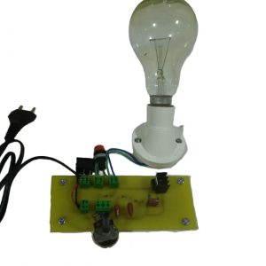
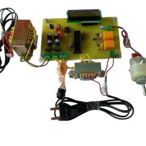
AC DIMMER TO CONTROL AC VOLTAGE, SPEED OF INDUCTION MOTOR OR HEATER COIL
$52.89$40.87A voltage controller, also called an AC voltage controller or AC regulator is an electronic module based on either thyristors, TRIACs, SCRs or IGBTs, which converts a fixed voltage, fixed frequency alternating current (AC) electrical input supply to obtain variable voltage in output delivered to a resistive load.
Induction motor speed control is done by varying the frequency of the applied voltage. Raising or lowering the voltage can have some speed control effects but these will be small, difficult to control, load-dependent, possibly cause the motor to overheat and, are not generally recommended.
-
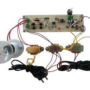
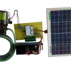
ACPWM power control using 555IC and IGBT
$62.50$50.48This project attempts a new speed control technique for the single-phase a.c. induction motor. It presents a design of a low-cost; high-efficiency drive capable of supplying a single-phase a.c. induction motor with a PWM modulated sinusoidal voltage. The circuit operation is controlled by 555 astable multivibrator. The device is aimed at substituting the commonly used triac phase angle control drives. The circuit is capable of supplying a single-phase a.c. induction motor (or general a.c. inductive/resistive load) with varying a.c. voltage.
-
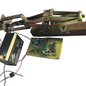
Android Controlled Car Jack
$276.46$264.44The project is designed to control the direction of car jack by using an android phone with the help of Bluetooth device. The direction of the DC motor is depending on the signal which is coming from mobile. Hence, if we press UP, this is present on your mobile then the relay1 & relay4 gets ON, so the motor rotates in forward direction. And if when we press DOWN from mobile the relay2 & realy3 gets ON then the motor rotates in backward direction.
-
ANDROID CONTROLLED HOME APPLIANCES USING PIC MICRO-CONTROLLER
$86.54$74.52The main objective of this project is to develop a home automation system with an Android application-controlled remote. As technology is advancing so houses are also getting smarter. Modern houses are gradually shifting from conventional switches to centralized control systems, involving wireless controlled switches.
-
AUTOMATIC IDENTIFICATION OF ELECTRICITY THEFT
$125.01$112.99In proposed system automatic identification of electricity theft using arduino. If we implement the project for a complete network of a area which will be consuming a very huge amount of energy. Here we are using arduino board, LCD display, current sensor, buzzer. And here in this project we can calculate the energy or power transmitted by the KEB and the energy consumed by the network of area. If both transmitted power by the KEB and the consumed power by the area differ by a large value the arduino will display these difference in the power reading on the LCD and the buzzer located in the KEB starts beeping indicating theft of electricity. As total Power losses equals transmission power losses plus distribution power losses.
-
AUTOMATIC POWER FACTOR CORRECTION USING PIC- MICROCONTROLLER
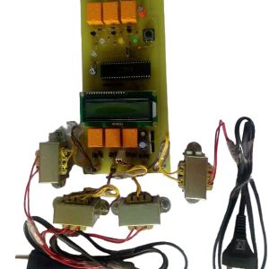
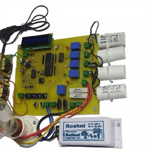
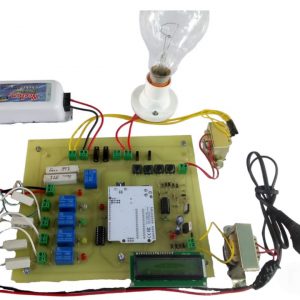
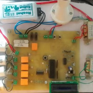
$100.97$90.15In this proposed system, two zero crossing detectors are used for detecting zero crossing of voltage and current. The project is designed to minimize penalty for industrial units using automatic power factor correction unit. The PIC microcontroller used in this project .
The time lag between the zero-voltage pulse and zero-current pulse is duly generated by suitable operational amplifier circuits in comparator mode is fed to two interrupt pins of a microcontroller. The program takes over to actuate appropriate number of relays from its output to bring shunt capacitors into load circuit to get the power factor till it reaches near unity.

