


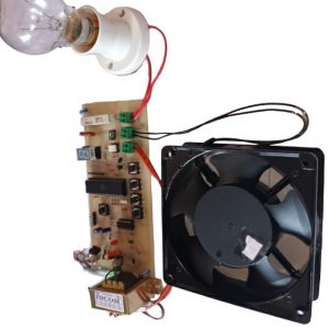


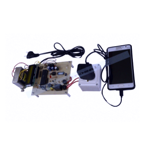
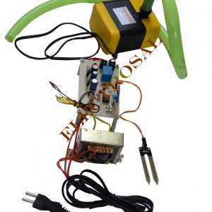
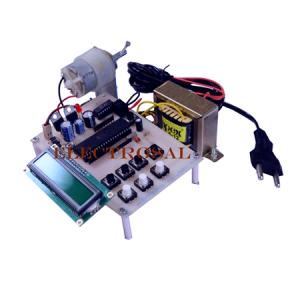
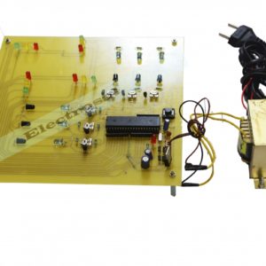
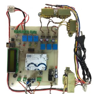
This project attempts a new speed control technique for the single-phase a.c. ????induction motor. It presents a design of a low-cost; high-efficiency drive capable of supplying a single-phase a.c. ????induction motor with a PWM modulated sinusoidal voltage. The circuit operation is controlled by an 8051 family microcontroller. The device is aimed at substituting the commonly used triac phase angle control drives. The circuit is capable of supplying a single-phase a.c. induction motor (or general a.c. inductive/resistive load) with varying a.c. voltage. The same as in triac control, the voltage applied to the load can be varied from zero to maximum value. On the other hand, it uses a pulse width modulation technique (PWM), and when compared with the phase angle control used for triacs, produces much lower high order harmonics. Thus, it suits EMC/EMI regulations much better. Because the circuit is aimed at low-cost, low/medium-power applications, it does not use a conventional converter topology to produce the output voltage waveform. It directly modulates the mains a.c. voltage. Compared with costly converter, it requires a lower number of active and passive power components. In summary, the device attempted here takes advantage of both the low price of the phase angle control and the low harmonic content and high efficiency that we can get with standard converter topology. The drive uses a PWM controlled MOSFET and the load in series with a bridge rectifier. This drive based on this new control technique is targeted for use in consumer and industrial products: washing machine, dishwashers, ventilators, compressors, and wherever the system cost is a consideration.
The input terminals of the rectifying bridge are connected in series to the load. The output terminals (rectified side) has a power transistor (IGBT, MOSFET or bipolar) connected across them. When the power transistor is off, current cannot flow through the rectifying bridge and the load which is in series remains in an off-state. When the power transistor is on, the bridge output terminals are short-circuited, then current can flow through the rectifying bridge and thus through the load. Thus by changing the duty cycle of the PWM pulses the power to the load is controlled. Special care is taken in the circuit such that the PWM pulses are synchronized with the supply phase by zero voltage sensing points.
??
Note
Speed control of induction motor using ACPWM the project of a good price for the engineering projects. It is a very comparative engineering project. It is a very good BE final year project. It is a project for core electrical based project. This project is embedded based project.
The engineering projects give in the ELECTROSAL HI- TECH PVT.LTD. The best place for the degree final year engineering projects as well as for core Electronics, Electrical and core electrical student???s final year for the golden opportunity.
Speed control of induction motor using ACPWM it is easy project and idea for the core electronics and electrical and core electrical, electronics base students and 100% output is done.
HIGHLIGHTS
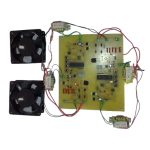
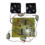
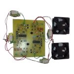
This project is for speed control technique for the single-phase a.c. induction motor
- An 8051 family microcontroller used.
- PWM technique
- MOSFET are used.
- Applications- washing machine, dishwashers, ventilators, compressors,
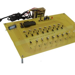
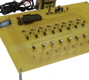
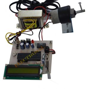
BLOCK DIAGRAM

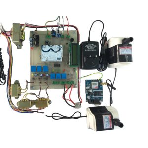
HARDWARE REQUIREMENTS
- 8051 family microcontroller
- MOSFET
- Bridge rectifier
- Single-phase A.C. induction motor
- Transformer
- ZCD
SOFTWARE REQUIREMENTS
- Eagle
- keil
- proteus

Aditya mane –
Excellent
Veeraj patil –
???ELECTRIC LINE MAN SAFETY WITH PASSWORD BASED CIRCUIT BREAKER??? from ELECTROSAL website and I felt very happy about this project and the support received from electrosal team is also good a I have called several times for support they given good response and immediately solved my queries as I submitted my project successfully.
Durgesh Jagatap –
Project was very good and works properly. Project report was also best.